

4 to 1 Rescue Pulley System: Buyer Guide
In technical rescue, a 4:1 designation describes a mechanical relationship, not a guarantee that a team can move any load with one-quarter the effort. The result depends on how the rope, pulleys, anchors, connectors, and progress-capture components are arranged and loaded.
Request a quote for a requirements-specific rescue system review.
A 4 to 1 rescue pulley system provides an ideal theoretical advantage of four units of rope travel for approximately one unit of load movement. While reducing the input force to roughly one-quarter of the load before friction and other losses. That tradeoff affects haul distance, operator planning, equipment selection, and procurement requirements.
To specify or deploy the system responsibly, start by separating the theoretical model from the complete load path. The arrangement determines what the four-to-one ratio means in practice and how the team should evaluate rope travel, component ratings, and system compatibility.
What Does a 4 to 1 Rescue Pulley System Actually Do?
A 4 to 1 rescue pulley system is a mechanical-advantage arrangement intended to reduce the hauling force required to move a load. In the ideal model, the rescuer pulls four feet of effort line for each one foot of load travel. While applying roughly one-quarter of the load force before accounting for system losses.
The ratio describes the relationship between effort-line travel and load travel, not a universal rating for the rope, pulleys, anchors, connectors, or the complete rescue system. Mechanical advantage can be evaluated by comparing the load weight with the effort-line force. Or by comparing how far the effort line moves with how far the load moves. In complex arrangements, simply counting supporting rope strands can produce an inaccurate result, so the actual rope path matters.
Why the 4:1 ratio is a planning model
In a theoretical 4:1 arrangement, four feet of rope movement produces one foot of load movement. That tradeoff can make a heavy or suspended load more manageable, but it also requires substantial haul-line travel. A rescue team must plan for available rope, clearance, anchor location, edge geometry, and the point at which the system may need to be reset or repositioned.
Theoretical advantage is not the same as field efficiency. Rope bending, pulley friction, connector alignment, sheave condition, rope diameter, and the geometry of the loaded system all consume part of the available advantage. The force required may therefore be greater than the ideal one-quarter estimate, and the load path may behave differently as angles or contact points change.
What the pulley hardware does, and does not establish
A component's published strength or working-load information applies to that specific component under its stated conditions. It does not automatically validate a complete 4:1 configuration. For example, Fusion's 34 kN rescue pulley specifications describe that product only; they should not be treated as a rating, compatibility statement, or certification for an assembled rescue system without requirements-specific verification.
Professional selection therefore starts with the complete load path: rope routing, anchors, pulleys, connectors, progress capture, and the intended rescue procedure. The ratio explains how the system is expected to work. Engineering evidence and trained operational practice determine whether a particular configuration is appropriate.
How Do Simple and Compound 4:1 Systems Change the Load Path?
Direct answer: A simple 4:1 routes one continuous rope through pulleys attached to the anchor and load. While a compound 4:1 combines two 2:1 systems so one system pulls on the other. Both can produce a theoretical 4:1 mechanical advantage, but they distribute rope tension, movement, and hardware loading differently. The complete load path includes the anchor system, rope, pulleys, connectors, progress capture, and load, not the pulley alone.
| Configuration | Basic routing | Load-path consideration | Planning implication |
|---|---|---|---|
| Simple 4:1 | One rope is threaded through pulleys at the anchor and load, creating multiple rope segments between those points. | The anchor, load attachment, pulley side plates, sheaves, rope, and connectors share a continuous system path. A simple arrangement is commonly described as having four supporting strands, but strand counting can mislead in complex layouts. | Check whether the available anchor-to-load distance and rope travel support the intended raise. Routing may also require a piggyback arrangement when space is limited. |
| Compound 4:1 | One 2:1 system is connected to the moving end of another 2:1 system. The mechanical advantages multiply in the ideal model. | The first system does not simply duplicate the second. Its moving pulley, connection point, rope, and capture method become part of the force path acting on the other system. | Inspect each subsystem and the interface between them. A failure, incompatibility, or unfavorable angle at that interface can affect the entire arrangement. |
The anchor system deserves particular attention. A technical-rescue anchor system is one or more anchor points arranged to provide a structurally significant connection for rope-rescue components. So the anchor structure and its connections must be evaluated as part of the rigging plan. The rope path should then be traced from the load, through every pulley and connector, to the anchor and haul side. This makes force direction, contact points, edge exposure, and progress-capture location visible before loading begins.
Do not treat a marked pulley rating as certification for the full system. A component rating describes that component under defined conditions. It does not by itself establish the capacity of the rope, anchor, connector, attachment point, progress-capture method, or the assembled configuration. Counting four strands also cannot replace configuration-specific analysis, since complex systems may not produce the assumed mechanical advantage. For procurement, request evidence for the complete intended arrangement and verify compatibility rather than transferring one product's rating to another.
For related component context, review the 34 kN rescue pulley specifications, then confirm that any selected hardware is appropriate for the actual system design and use case.
How Do Friction, Rope Travel, and Operator Roles Affect the Plan?
Direct answer: A 4 to 1 rescue pulley system reduces the ideal effort needed to move a load, but it also requires proportionally more rope travel. Friction, pulley efficiency, rope path, anchor geometry, and progress capture determine how the system performs in the field. The number of operators must therefore be established by a qualified rescue team for the specific configuration, load, environment, and procedure, not promised as a universal count.
Mechanical advantage is a relationship between load movement and effort-line movement. In an ideal 4:1 model, approximately four feet of rope travel produces one foot of load travel. While the required effort is reduced to roughly one-quarter of the load weight. Those figures describe a theoretical arrangement, not a guaranteed field result. The academic primer explains that comparing effort-line travel with load travel is one way to determine mechanical advantage. While simply counting supporting rope segments can be inaccurate in complex systems: review the pulley-systems primer.
Friction consumes part of the theoretical advantage. Sheave condition and alignment, rope diameter, bends, connector placement, edge contact, and the routing of the rope can all increase resistance. A system may still provide meaningful assistance, but the operator should not treat a 4:1 label as a component rating. A measured efficiency value, or permission to exceed the ratings of any pulley, rope, anchor, connector, or capture device.
Rope travel also affects the work plan. A longer haul may require the team to reset the system, move an adjustable hauling arrangement along the haul line. Or coordinate progress capture so that gained elevation is not lost during a reset. The primer notes that adjustable rescue hauling systems can be repositioned along the haul line, but the correct method depends on the trained system design and operating procedure.
Operator roles should be planned around responsibilities rather than a fixed headcount. The team may need distinct functions for haul coordination, progress-capture control, load monitoring, anchor oversight, communications, and safety observation. Massachusetts guidance identifies teamwork and experience as potential factors in technical-rescue failures. While Connecticut Fire Academy curriculum treats inspection, anchors, mechanical advantage, team roles, and safety as separate training subjects. Those references reinforce the planning principle, but they do not replace site-specific training or establish one universal staffing requirement.
Before deployment, the authority having jurisdiction and qualified instructors should validate the complete load path, communication method, reset procedure, and contingency actions for the intended operation. Equipment documentation can support that plan, but it cannot substitute for competency in the configured system.
Which Specifications Should Buyers Require Before Ordering?
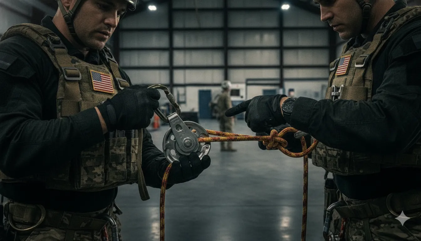
Require a specification package that defines the intended rescue use, complete load path, working length. Rope and terminations, pulley configuration, connectors, progress capture, ratings, applicable standards, training, storage, and traceability. A 4 to 1 rescue pulley system should be evaluated as an integrated arrangement, not as a pulley count or a theoretical ratio. Commercial kits can illustrate the fields procurement teams should request, but their ratings and certifications must not be transferred to another product or configuration.
Start with the operational requirement. Document whether the system is intended for raising, lowering, confined-space access, assisted rescue, or another defined procedure. Specify the expected load, anchor arrangement, edge geometry, available haul space, and the working length needed at the site. Working length is not simply rope inventory. It must account for the system's routing, travel, resets, and the distance between the anchor and load.
- Rope: Require the approved diameter, construction, length method, and termination type. State whether terminations are sewn, knotted, or another engineered arrangement. A commercial example lists 11 mm static rope with sewn terminations, but that is an example of a specification field, not a universal requirement.
- Pulleys and sheaves: Identify the exact pulley type, sheave geometry, rope compatibility, side-plate or capture design, bearing details where relevant, and evidence supporting the intended use. Keep each component's minimum breaking strength and working-load limit tied to its own documentation.
- Connectors and capture: Define connector type, gate and locking requirements, orientation controls, and how hauling progress is captured. Confirm whether capture is integrated or supplied separately, and document the release or descent procedure.
- Ratings and standards: Request a component-by-component rating schedule, test reports, inspection criteria, and the standard edition and scope used for each claim. A competitor listing may cite standards such as EN 12278 or NFPA provisions, but that does not establish compliance for another system.
- Readiness and traceability: Require user training, inspection and storage instructions, serial or lot identification, revision-controlled drawings, operating limits, and records that connect supplied parts to the approved configuration.
For complex programs, procurement teams should involve engineering before issuing a purchase order. Fusion Tactical's engineering and testing capabilities can support requirements analysis and verification planning, while custom equipment configurations provide a route for mission-specific hardware questions. Neither page should be read as a certification of an unverified 4:1 system. The approval package should identify exactly what was designed, tested, supplied, and accepted.
What Should Inspection and Readiness Procedures Cover?
A readiness procedure for a 4 to 1 rescue pulley system should evaluate the complete load path, not just the pulleys. It should combine pre-use checks, scheduled maintenance, competent personnel, contamination controls, removal-from-service criteria. And records that show what was inspected and why the system remains fit for its intended operation.
The procedure should also define who may inspect, rig, supervise, and operate the system. Technical-rescue training references treat inspection and maintenance, anchors, mechanical-advantage systems, team roles, and safety as distinct but connected areas, rather than as one equipment check.
- Confirm the plan and personnel. Verify the intended load, route, anchor arrangement, rope path, pulley configuration, connectors, progress-capture method, and communication plan. Assign roles to trained personnel who understand the equipment and the operation. A Massachusetts technical-rescue manual identifies teamwork and experience as potential failure factors, so readiness includes coordination, not only hardware condition. Review the technician-level training reference.
- Complete a pre-use inspection. Examine the rope for cuts, glazing, abrasion, contamination, stiffness, damage, or questionable terminations. Check pulley sheaves, side plates, axles, bearings, attachment points, and markings. Inspect carabiners and other connectors for deformation, gate or locking problems, cracks, corrosion, and smooth operation. Check anchors and anchor connections for structural significance, correct orientation, and unintended movement.
- Test the assembled function without loading beyond the plan. Confirm that the rope follows the intended route, pulleys rotate, connectors remain closed and oriented correctly, and the progress-capture device engages and releases as designed. Do not assume that counting rope strands proves the system is correctly rigged. Verify the actual configuration against the team's approved procedure.
- Control contamination and storage. Keep rope and hardware away from chemicals, sharp edges, excessive heat, moisture, and unnecessary ground contact. Store clean, dry, protected equipment in a way that prevents crushing, tangling, ultraviolet exposure, and unrecorded substitution. Follow the applicable manufacturer instructions for cleaning and care.
- Define removal from service and records. Quarantine equipment after damage, abnormal loading, suspected contamination, failed inspection, or uncertain history. Record equipment identity, inspection date, findings, corrective action, and the qualified person's disposition. Set scheduled inspection frequencies through the team's governing procedure and manufacturer guidance, rather than inventing a universal interval. Training curricula can standardize a team's method, but they do not cover every acceptable rescue method. See the Connecticut Fire Academy curriculum context.
How Can Procurement Teams Validate a 4:1 Rescue System Partner?
Direct answer: Validate the partner by tracing every requirement to a documented component, configuration, test boundary, and sourcing statement. A capable supplier should explain what it designs and verifies, what remains customer- or operator-controlled. And which compliance claims apply to the specific equipment rather than to the company in general.
Start with a requirements traceability review. Define the intended rescue scenario, load path, rope and termination requirements, working length, connectors, progress capture, inspection needs, and training assumptions. Then require a configuration-level bill of materials and evidence for each component. A 4:1 mechanical-advantage label does not establish a system rating, compatibility, or suitability for a particular rescue operation. Treat the pulley, rope, anchors, connectors, capture device, and load as one engineered system, and do not transfer a rating from one product to another.
Next, separate evidence of capability from evidence of a completed test. Fusion Tactical's documented scope includes requirements analysis, design, prototyping, testing, and production scaling. Its engineering process also includes in-house and third-party strength and load testing and verification. Those capabilities support a disciplined development conversation, but they do not mean an unspecified 4:1 configuration has already been tested. Ask for the proposed test method, fixture and load conditions, acceptance criteria, limitations, and the exact configuration covered by the result. Review Fusion's engineering and testing capabilities alongside the requirements package.
Domestic sourcing and compliance deserve their own verification track. Confirm the manufacturing location, supply-chain documentation, and any program-specific sourcing requirement. Berry Amendment capability and Trade Agreements Act, or TAA, considerations should not be treated as interchangeable, and neither should be presented as a blanket certification for every component. Standards and compliance claims depend on the specific equipment and intended use. Procurement teams can review Fusion's government and defense procurement capabilities and Berry-compliant manufacturing capabilities, then request the documentation applicable to their contract.
Finally, assess whether the supplier can adapt the design without obscuring system boundaries. Fusion's custom equipment configurations offering is relevant when the requirement involves an integrated rescue or load-bearing solution. The objective is not to assume Fusion sells a 4:1 kit. It is to determine whether the proposed partner can convert an operational requirement into a documented, testable, and procurement-ready configuration.
Contact Fusion Tactical to request a quote or engineering consultation.
Frequently Asked Questions
What is the mechanical advantage of a 4:1 rescue pulley system?
It is a theoretical 4:1 mechanical advantage. Meaning the ideal effort is approximately one-quarter of the load force while the operator pulls about four feet of rope for each foot of load movement. Friction, pulley efficiency, rope routing, and system geometry reduce real-world performance, so the ratio is not a product rating.
Is a simple 4:1 different from a compound 4:1?
Yes. A simple arrangement uses one rope routed through pulleys between the anchor and load, while a compound arrangement can connect two 2:1 systems in series. The layout changes the rope path, travel, reset procedure, and how forces reach each component. So the complete rig should be evaluated rather than identified by pulley count alone.
How much rope travel does a 4:1 system require?
As an ideal planning model, four feet of haul-line travel produces one foot of load movement. Actual travel depends on the chosen configuration, available working length, friction, and how often the system must be reset. Confirm the required travel against the rescue plan and site geometry before specifying rope length.
Does a 4:1 ratio determine the system rating?
No. The ratio describes mechanical advantage, not working load, minimum breaking strength, or compatibility. Buyers should verify the rating and evidence for the rope, pulleys, connectors, anchors, progress-capture device, terminations, and complete configuration. Never transfer a rating from one component or commercial kit to another.
Which standards apply to a 4:1 rescue pulley system?
There is no single standard that automatically certifies every 4:1 configuration. Applicability depends on the equipment category, intended use, jurisdiction, and procurement requirement. Request product-specific test records, instructions, traceability, and a clear statement of which standard provisions apply before approval.
Contact Us to Specify Your Rescue System
A requirements-specific review can help your team align the 4:1 system configuration, rated hardware, load paths, and documentation with the intended application. Contact us to request a quote or engineering consultation about custom equipment configurations.


